实验 – 配置 IPv4 静态路由和默认路由(教师版)步骤在末尾,报告结束以后(二十步解决,不用听课,闭着眼照着步骤做就没问题)
最后更新:2022-04-28 09:07:04 手机定位技术交流文章
用 IPv4 静态和默认路径实验(教师版本)。
教师注意:只有教师副本上的文字用红字或灰色突出区域表示。
拓扑
地址分配表
IP 地址 IP 子网罩默认网关设备接口
R1 G0/1 192.168.0.1 255.255.255.0 N/A
S0/0/1 10.1.1.1 255.255.255.252 N/A
R3 G0/1 192.168.1.1 255.255.255.0 N/A
S0/0/0 (DCE) 10.1.1.2 255.255.255.252 N/A
Lo0 209.165.200.225 255.255.255.224 N/A
Lo1 198.133.219.1 255.255.255.0 N/A
PC-A NIC 192.168.0.10 255.255.255.0 192.168.0.1
PC-C NIC 192.168.1.10 255.255.255.0 192.168.1.1
目标
第1部分:设备安装和启动
构成部分2:建立基本设备设置和重复检查连接。
步骤3:建立静态路线
静态路线的后向配置 。
设置直线和固定的路线。
可以配置和删除静态路线。
第4部分:设置和测试默认路径
背景/场景
路由器使用路由器表格来决定数据包的交付地点。路由器图包括一组路由器集,其中说明路由器用于到达给定网络的网关或界面。最初,路由器列表仅包括直接连接的网络。要与远程网络互动,就必须指定路线,并将其添加到路由器列表中,以决定数据包的交付地点。路由器图集包括一组路由器集,其中说明路由器使用的网关或界面进入给定网络。最初,路由列表仅包括直接连接的网络。要与远程网络互动,就必须指定路线并添加到路由器列表中。
在此实验中, 您将根据下一个跳跃 IP 地址或传输界面, 手动指向给定远程网络的静态路径。 无法初始化 Evolution 的邮件组件 。 默认路径是一个静态路径, 用于定义当路由路由路由器不包含通往目的网络的路径时要使用的网关 。
N.B. 但是,需要的命令载于附录A。 试图在不参考附录的情况下设置装置,并测试你的理解程度。
N.B. Cisco IOS 版本15. Cisco 1941年2(4)M3(通用K9图像)的综合多业务路由器(ISR),用于CCNA亲手操作练习。Cisco IOS 版本15. Cisco Catalyst 2960系列开关已经使用。还有许多其他路由器、开关和Cisco IOS版本。根据模型和Cisco IOS版本,现有说明和产出可能不同于试验中显示的说明和产出。关于正确的接口标识,请见试验结束时的路由器界面总表。
注:如果路由器和开关启动配置未擦除,请与教师联系。
关于设备启动和重新装填方法的细节,请参考《教师实验手册》。
所需资源
**2 路由器(支持Cisco IOS 15)(2)(4)(4)M3 General image Cisco 1941或类似路由器)
**2开关(支持Cisco IOS 15版)。 (2) Lanbasek9 图像需要一个 Cisco 2960 或类似的开关)。
**2 计算机(运行视窗7、Vista或XP,能够运行终端模拟软件,如Terra Terrance)
控制台电缆用于通过控制台端口配置 Cisco IOS 设备 。
如Tate所示,以太网线和连线电缆
第1部分:设备安装和启动
步骤 1: 创建在上到下图中描述的网络 。
步骤2:重新装载和启动路由器和开关。
构成部分2:建立基本设备设置和重复检查连接。
在第2部分,您将建立基本的设置, 如接口 IP 地址、 设备访问权限和密码。 您还将测试局域网连接, 并确定 R1 和 R3 路径列表中提到的路径 。
第1步: 设置 PC 接口 。
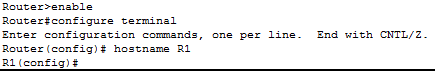
步骤2: 配置路由器的基本设置 。
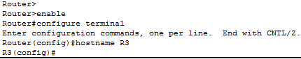
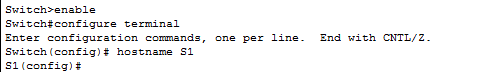
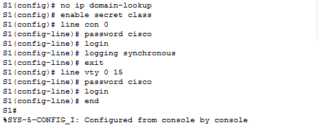
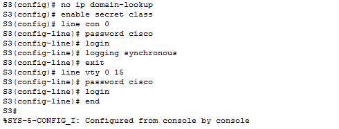
a. 将东岛和地址分配表显示的设备名称配置成像 。
b. 残疾DNS检查。
c. 指定类为推进器密码,Cisco为控制器密码和 vty 密码。
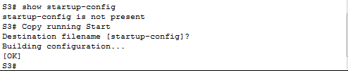
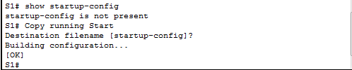
d. 将当前配置写入启动配置文件。
第3步:在路由器上设定IP地址。
a. 使用地址分配表为 R1 和 R3 接口配置 IP 地址。
b. S0/0/0连接是一个DCE连接,需要使用块速率命令。 R3 S0/0配置如下。
注意教师: Cisco 1941路由器自动检测DCE, 将时钟频率调整为200 00, 没有设置 。
R3(config)# interface s0/0/0
R3(config-if)# ip address 10.1.1.2 255.255.255.252
R3(config-if)# clock rate 128000
R3(config-if)# no shutdown
步骤4:将局域网连接与测试连接。
一、关于《公约》及其《京都议定书》的《公约》 和《公约》的《公约》的《公约》的《公约》缔约国和《公约》的《公约》缔约国和《公约》缔约方的《公约》缔约方的《公约》缔约方的《公约》缔约方的《公约》缔约方的《公约》缔约方的《公约》缔约方的《公约》缔约方的《公约》缔约方的《公约》缔约方的《公约》缔约方的《公约》缔约方和《公约》缔约方的《公约》缔约方的《公约》缔约方的 《公约》缔约方的《公约》缔约方的《公约》缔约方和《公约》缔约方的《公约》缔约方的《公约》
您可以在PC-A的默认网关上运行 ping 操作吗?
您可以在PC-C的默认网关上做 ping 操作吗?
b. 在两个直接连接路由器之间进行连接操作,以测试连接。
R3 的 S0 0/ 0 接口能否从 R1 中用于 ping 操作?
如果你对任何问题都回答不,请删除设置并纠正问题。
c. 测试非直接连接设备之间的连接。
你能为PC -C做PC -A的 Ping 操作吗?
你能为LO0做PC-A的 ping 操作吗?
您能否为 Lo1 在 PC-A 做 Ping 操作?
这些刺线有效吗?
由于未安装路由器,所以在运抵时找不到路由器。
必须指出的是,个人计算机之间的平线操作可能需要使个人计算机防火墙失效。
步骤5:信息收集。
5 5 5 5 5 5 5 5 5 5 5 5 5 5 5 5 5 5 5 5 5 5 5 5 5 5 5 5 5 5 5 5 5 5 5 5 5 5 5 5 5 5 5 5 5 5 5 5 5 5 5 5 5 5 5 5 5 5 5 5 5 5 5 5 5 5 5 5 5 5 5 5 5 5 5 5 5 7 5 5 5 5 5 5 5 5 5 5 5 5 5 5 5 5 5 5 5 5 5 5 5 5 5 5 5 5 5 5 5 5 5 5 5 5 5 5 5 5 5 5 5 5 5 5 5 5 5 5 5 5 5 5 5 5 5 5 5 5 5 5 5 5 5 5 5 5 5 5 5 5 5 5 5 5 5 5 5 5 5 5 5 5 5 5 5 5 5 5 5 5 5 5 5 5 5 5 5 5 5 5 5 5 5 5 5 5 5 5 5 5 5 5 5 5 5 5 5 5 5 5 5 5 5 5 5 5 5 5 5 5 5 5 5 5 5 5 5 5 5 5 5 5 5 5 5 5 5 5 5 5 5 5 5 5 5 5 5 5 5 5 5 5 5 5 5 5 5 5 5 5 5 5 5 5 5
R1# show ip interface brief
Interface IP-Address OK? Method Status Protocol
Embedded-Service-Engine0/0 unassigned YES unset administratively down down
GigabitEthernet0/0 unassigned YES unset administratively down down
GigabitEthernet0/1 192.168.0.1 YES manual up up
Serial0/0/0 unassigned YES unset administratively down down
Serial0/0/1 10.1.1.1 YES manual up up
在 R1 上激活了多少个接口?
b. 验证R3的接口状态。
R3# show ip interface brief
Interface IP-Address OK? Method Status Protocol
Embedded-Service-Engine0/0 unassigned YES unset administratively down down
GigabitEthernet0/0 unassigned YES unset administratively down down
GigabitEthernet0/1 192.168.1.1 YES manual up up
Serial0/0/0 10.1.1.2 YES manual up up
Serial0/0/1 unassigned YES unset administratively down down
Loopback0 209.165.200.225 YES manual up up
Loopback1 198.133.219.1 YES manual up up
在R3上,有多少接口在活动?
c. 使用显示 ip 根命令查看 R1 路径细节。
R1# show ip route
Codes: L - local, C - connected, S - static, R - RIP, M - mobile, B - BGP
D - EIGRP, EX - EIGRP external, O - OSPF, IA - OSPF inter area
N1 - OSPF NSSA external type 1, N2 - OSPF NSSA external type 2
E1 - OSPF external type 1, E2 - OSPF external type 2
i - IS-IS, su - IS-IS summary, L1 - IS-IS level-1, L2 - IS-IS level-2
ia - IS-IS inter area, * - candidate default, U - per-user static route
o - ODR, P - periodic downloaded static route, H - NHRP, l - LISP
+ - replicated route, % - next hop override
Gateway of last resort is not set
C 10.1.1.0/30 is directly connected, Serial0/0/1
L 10.1.1.1/32 is directly connected, Serial0/0/1
192.168.0.0/24 is variably subnetted, 2 subnets, 2 masks
C 192.168.0.0/24 is directly connected, GigabitEthernet0/1
L 192.168.0.1/32 is directly connected, GigabitEthernet0/1
本实验的地址分配表中存在哪些网络,而R1的路线表中则没有?
C 192.168.0.0/24 is directly connected, GigabitEthernet0/1
d. 查看R3的路线表信息。
R3# show ip route
Codes: L - local, C - connected, S - static, R - RIP, M - mobile, B - BGP
D - EIGRP, EX - EIGRP external, O - OSPF, IA - OSPF inter area
N1 - OSPF NSSA external type 1, N2 - OSPF NSSA external type 2
E1 - OSPF external type 1, E2 - OSPF external type 2
i - IS-IS, su - IS-IS summary, L1 - IS-IS level-1, L2 - IS-IS level-2
ia - IS-IS inter area, * - candidate default, U - per-user static route
o - ODR, P - periodic downloaded static route, H - NHRP, l - LISP
+ - replicated route, % - next hop override
Gateway of last resort is not set
C 10.1.1.0/30 is directly connected, Serial0/0/0
L 10.1.1.2/32 is directly connected, Serial0/0/0
192.168.1.0/24 is variably subnetted, 2 subnets, 2 masks
C 192.168.1.0/24 is directly connected, GigabitEthernet0/1
L 192.168.1.1/32 is directly connected, GigabitEthernet0/1
198.133.219.0/24 is variably subnetted, 2 subnets, 2 masks
C 198.133.219.0/24 is directly connected, Loopback1
L 198.133.219.1/32 is directly connected, Loopback1
209.165.200.0/24 is variably subnetted, 2 subnets, 2 masks
C 209.165.200.224/27 is directly connected, Loopback0
L 209.165.200.225/32 is directly connected, Loopback0
本实验的地址分配表中存在哪些网络,而R3的路线表中则没有?
为什么路由器的路由器名单上没有所有网络?
步骤3:建立静态路线
第3部分将看到你们采用若干方法执行静态和默认路线,确认线路已被列入R1和R3路线清单,并根据你们介绍的路线检查连接。
N.B. 但是,需要的命令载于附录A。 试图在不参考附录的情况下设置装置,并测试你的理解程度。
第1步:创建静态路线。
递归静态路径指定了下一个跳跃 IP 地址。 因为仅提供了下一个跳跃 IP 地址, 路由器在发送数据包之前必须在路由器表格中进行多次搜索。 要设置递减静态路径, 请使用以下语法 :
Router(config)# ip route network-address subnet-mask ip-address
a..## 配置 R1路由器的静态路径到网络(IP 地址, 使用 R3 序列 0/ 0/ 0 接口作为下一个跳跃地址) 。 输入您在下面区域使用的命令 。
R1(config)# ip route 192.168.1.0 255.255.255.0 10.1.1.2
b. 探索路线图并寻找新增加的静态路线条目。
R1# show ip route
Codes: L - local, C - connected, S - static, R - RIP, M - mobile, B - BGP
D - EIGRP, EX - EIGRP external, O - OSPF, IA - OSPF inter area
N1 - OSPF NSSA external type 1, N2 - OSPF NSSA external type 2
E1 - OSPF external type 1, E2 - OSPF external type 2
i - IS-IS, su - IS-IS summary, L1 - IS-IS level-1, L2 - IS-IS level-2
ia - IS-IS inter area, * - candidate default, U - per-user static route
o - ODR, P - periodic downloaded static route, H - NHRP, l - LISP
+ - replicated route, % - next hop override
Gateway of last resort is not set
C 10.1.1.0/30 is directly connected, Serial0/0/1
L 10.1.1.1/32 is directly connected, Serial0/0/1
192.168.0.0/24 is variably subnetted, 2 subnets, 2 masks
C 192.168.0.0/24 is directly connected, GigabitEthernet0/1
L 192.168.0.1/32 is directly connected, GigabitEthernet0/1
S 192.168.1.0/24 [1/0] via 10.1.1.2
新路线在地图上如何出现?
C 192.168.0.0/24 is directly connected, GigabitEthernet0/1
您能否为主机PC- A的主机 PC- C 做 Ping 操作?
这些电话不会成功。如果固定路线的其余部分设置得当,Ping能够达到PC-C。PC-A对 ping 的回答由 PC-C 返回 。然而,在R3上, ping 回答将被忽略 。因为R3路线清单没有返回网络的路线。
第2步:建立静态路线直线。
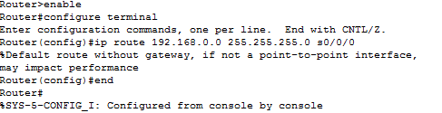
通过使用直静态路径,提供退出界面参数,并允许路由器通过搜索发送决定。直接静态路由器通常用于点对点字符串界面。要对直静路径使用指定的交付界面配置,请使用以下语法:
Router(config)# ip route network-address subnet-mask exit-intf
a.. at.. on the R3 路由器, 配置连接网络的静态路径, 使用 S0/ 0/ 0 作为传输界面 。 写入您在下面的空格中使用的命令 。
R3(config)# ip route 192.168.0.0 255.255.255.0 s0/0/0
b. 探索路线图并寻找新增加的静态路线条目。
R3# show ip route
Codes: L - local, C - connected, S - static, R - RIP, M - mobile, B - BGP
D - EIGRP, EX - EIGRP external, O - OSPF, IA - OSPF inter area
N1 - OSPF NSSA external type 1, N2 - OSPF NSSA external type 2
E1 - OSPF external type 1, E2 - OSPF external type 2
i - IS-IS, su - IS-IS summary, L1 - IS-IS level-1, L2 - IS-IS level-2
ia - IS-IS inter area, * - candidate default, U - per-user static route
o - ODR, P - periodic downloaded static route, H - NHRP, l - LISP
+ - replicated route, % - next hop override
Gateway of last resort is not set
C 10.1.1.0/30 is directly connected, Serial0/0/0
L 10.1.1.2/32 is directly connected, Serial0/0/0
S 192.168.0.0/24 is directly connected, Serial0/0/0
192.168.1.0/24 is variably subnetted, 2 subnets, 2 masks
C 192.168.1.0/24 is directly connected, GigabitEthernet0/1
L 192.168.1.1/32 is directly connected, GigabitEthernet0/1
198.133.219.0/24 is variably subnetted, 2 subnets, 2 masks
C 198.133.219.0/24 is directly connected, Loopback1
L 198.133.219.1/32 is directly connected, Loopback1
209.165.200.0/24 is variably subnetted, 2 subnets, 2 masks
C 209.165.200.224/27 is directly connected, Loopback0
L 209.165.200.225/32 is directly connected, Loopback0
新路线在地图上如何出现?
S 192.168.0.0/24 is directly connected, Serial0/0/0
c. 您能否为主机PC-A的主机 PC-C 执行 Ping 操作?
必须指出的是,个人计算机之间的平线操作可能需要使个人计算机防火墙失效。
第3步:设置静态路线。
a.. at the R1 路由器上,使用前一步的静态路由配置选项之一配置到网络的静态路由。 写入您在下面的空格中使用的命令 。
R1(config)# ip route 198.133.219.0 255.255.255.0 S0/0/1
b. 在R1路由器上前一步使用另一个静态路线配置选项,以配置 R3. 写入您在下面区域所使用的命令 。
R1(config)# ip route 209.165.200.224 255.255.255.224 S0/0/1
or
R1(config)# ip route 209.165.200.224 255.255.255.224 10.1.1.2
c. 探索路线图并寻找新增加的静态路线入口。
注:学生可产生多种产出路线表,视已建立的静态路线类型而定。
R1# show ip route
Codes: L - local, C - connected, S - static, R - RIP, M - mobile, B - BGP
D - EIGRP, EX - EIGRP external, O - OSPF, IA - OSPF inter area
N1 - OSPF NSSA external type 1, N2 - OSPF NSSA external type 2
E1 - OSPF external type 1, E2 - OSPF external type 2
i - IS-IS, su - IS-IS summary, L1 - IS-IS level-1, L2 - IS-IS level-2
ia - IS-IS inter area, * - candidate default, U - per-user static route
o - ODR, P - periodic downloaded static route, H - NHRP, l - LISP
+ - replicated route, % - next hop override
Gateway of last resort is not set
C 10.1.1.0/30 is directly connected, Serial0/0/1
L 10.1.1.1/32 is directly connected, Serial0/0/1
192.168.0.0/24 is variably subnetted, 2 subnets, 2 masks
C 192.168.0.0/24 is directly connected, GigabitEthernet0/1
L 192.168.0.1/32 is directly connected, GigabitEthernet0/1
S 192.168.1.0/24 [1/0] via 10.1.1.2
S 198.133.219.0/24 is directly connected, Serial0/0/1
209.165.200.0/27 is subnetted, 1 subnets
S 209.165.200.224 [1/0] via 10.1.1.2
新路线在地图上如何出现?
S 198.133.219.0/24 is directly connected, Serial0/0/1
d. 您能否使用主机PC-A在 R1 地址上做一个 ping?
第4步:删除循环的静态路径返回地址。
在 R1 上, 没有命令可以删除两个循环返回表格地址的静态路径。 写入您在下面空格中使用的命令 。
R1(config)# no ip route 209.165.200.224 255.255.255.224 10.1.1.2
R1(config)# no ip route 198.133.219.0 255.255.255.0 S0/0/1
应当指出,任何指令都不得用于清除静态路由器,而不具体说明接口或下一个IP跳跃地址。
R1(config)# no ip route 209.165.200.224 255.255.255.224
R1(config)# no ip route 198.133.219.0 255.255.255.0
b. 检查路线文件,检查是否已经删除。
R1# show ip route
Codes: L - local, C - connected, S - static, R - RIP, M - mobile, B - BGP
D - EIGRP, EX - EIGRP external, O - OSPF, IA - OSPF inter area
N1 - OSPF NSSA external type 1, N2 - OSPF NSSA external type 2
E1 - OSPF external type 1, E2 - OSPF external type 2
i - IS-IS, su - IS-IS summary, L1 - IS-IS level-1, L2 - IS-IS level-2
ia - IS-IS inter area, * - candidate default, U - per-user static route
o - ODR, P - periodic downloaded static route, H - NHRP, l - LISP
+ - replicated route, % - next hop override
Gateway of last resort is not set
C 10.1.1.0/30 is directly connected, Serial0/0/1
L 10.1.1.1/32 is directly connected, Serial0/0/1
192.168.0.0/24 is variably subnetted, 2 subnets, 2 masks
C 192.168.0.0/24 is directly connected, GigabitEthernet0/1
L 192.168.0.1/32 is directly connected, GigabitEthernet0/1
S 192.168.1.0/24 [1/0] via 10.1.1.2
在R1路线清单中,列出了多少条网络路线?
您是否设置了最后一选网关?
第4部分:设置和测试默认路径
第4部分将看到您应用默认路线,确保它被添加到路线数据库中,并使用您建立的路线连接。
当未获得路径或静态路径时, 默认路径被用来识别所有 IP 包发送的网关。 默认静态路径是静态路径, 用作目的地 IP 地址和子网盖。 通常被称为“ 完全为零 ” 路径 。
您可以在默认路径中提供下一个跳跃 IP 地址或传输界面。 要定义默认静态路径, 请使用以下语法 :
Router(config)# ip route 0.0.0.0 0.0.0.0 {ip-address or exit-intf}
a..
R1(config)# ip route 0.0.0.0 0.0.0.0 s0/0/1
b. 探索路线图并寻找新增加的静态路线条目。
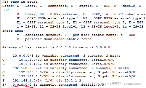
R1#show ip route
Codes: L - local, C - connected, S - static, R - RIP, M - mobile, B - BGP
D - EIGRP, EX - EIGRP external, O - OSPF, IA - OSPF inter area
N1 - OSPF NSSA external type 1, N2 - OSPF NSSA external type 2
E1 - OSPF external type 1, E2 - OSPF external type 2
i - IS-IS, su - IS-IS summary, L1 - IS-IS level-1, L2 - IS-IS level-2
ia - IS-IS inter area, * - candidate default, U - per-user static route
o - ODR, P - periodic downloaded static route, H - NHRP, l - LISP
+ - replicated route, % - next hop override
Gateway of last resort is 0.0.0.0 to network 0.0.0.0
S* 0.0.0.0/0 is directly connected, Serial0/0/1
10.0.0.0/8 is variably subnetted, 2 subnets, 2 masks
C 10.1.1.0/30 is directly connected, Serial0/0/1
L 10.1.1.1/32 is directly connected, Serial0/0/1
192.168.0.0/24 is variably subnetted, 2 subnets, 2 masks
C 192.168.0.0/24 is directly connected, GigabitEthernet0/1
L 192.168.0.1/32 is directly connected, GigabitEthernet0/1
S 192.168.1.0/24 [1/0] via 10.1.1.2
新路线在地图上如何出现?
S* 0.0.0.0/0 is directly connected, Serial0/0/1
最后一个出口是什么?
Gateway of last resort is 0.0.0.0 to network 0.0.0.0
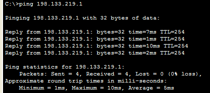
c. 你能运行主机PC-A的 ping 命令吗?
d. 你能运行主机PC-A的 ping 命令吗?
思考
在R1 G0/0中增加了一个新的网络/24接口。 设置从R3到网络的静态线路应使用何种命令?
R3(config)# ip route 192.168.3.0 255.255.255.0 g0/0/0
二. 配置一条静态直线路线而不是一条对等静态路线有什么好处?
没有必要重复很多次, 但是如果中间有其它网络静态网络, 它就无法运作。
第三,为什么必须配置路由器的默认路线?
由于没有默认路径, 因为目的地地址与路径检查之间没有匹配 。
路由器接口摘要表
路由器接口摘要
以太网接口 # 1 以太网接口 # 2 法律接口 # 1 法律接口 # 2 路由器模型
1800 Fast Ethernet 0/0 (F0/0) Fast Ethernet 0/1 (F0/1) Serial 0/0/0 (S0/0/0) Serial 0/0/1 (S0/0/1)
1900 Gigabit Ethernet 0/0 (G0/0) Gigabit Ethernet 0/1 (G0/1) Serial 0/0/0 (S0/0/0) Serial 0/0/1 (S0/0/1)
2801 Fast Ethernet 0/0 (F0/0) Fast Ethernet 0/1 (F0/1) Serial 0/1/0 (S0/1/0) Serial 0/1/1 (S0/1/1)
2811 Fast Ethernet 0/0 (F0/0) Fast Ethernet 0/1 (F0/1) Serial 0/0/0 (S0/0/0) Serial 0/0/1 (S0/0/1)
2900 Gigabit Ethernet 0/0 (G0/0) Gigabit Ethernet 0/1 (G0/1) Serial 0/0/0 (S0/0/0) Serial 0/0/1 (S0/0/1)
请记住,为了了解如何配置路由器,检查接口以确定路由器的类型及其拥有的接口数量。我们无法包含每个路由器类型的所有设置 。下表列出了与Tainet和序列接口结合的装置的识别号。本表格中没有其它类型的接口 。然而,真正的路由器可能有更多的接口。考虑ISDN BRI 接口。括号之间的字符串是商定的缩略语,要代表接口,请使用 Cisco IOS 命令。
附录A:第2、3和4部分的所需配置说明
附录A提到的命令主要出于信息原因,本附录不包括进行试验所需的所有特别命令。
设备的基本设置
配置路由器的 IP 设置 。
R3(config)# interface s0/0/0
R3(config-if)# ip address 10.1.1.2 255.255.255.252
R3(config-if)# clock rate 128000
R3(config-if)# no shutdown
静态路由配置
配置递归静态路由。
R1(config)# ip route 192.168.1.0 255.255.255.0 10.1.1.2
配置直连静态路由。
R3(config)# ip route 192.168.0.0 255.255.255.0 s0/0/0
删除静态路由。
R1(config)# no ip route 209.165.200.224 255.255.255.224 serial0/0/1
R1(config)# no ip route 209.165.200.224 255.255.255.224 10.1.1.2
R1(config)# no ip route 209.165.200.224 255.255.255.224
默认路由配置
R1(config)# ip route 0.0.0.0 0.0.0.0 s0/0/1
R1和R3设备配置
R1路由器(第4部分后)
R1#show run
Building configuration…
Current configuration : 1547 bytes
!
version 15.2
service timestamps debug datetime msec
service timestamps log datetime msec
service password-encryption
!
hostname R1
!
boot-start-marker
boot-end-marker
!
!
enable secret 4 06YFDUHH61wAE/kLkDq9BGho1QM5EnRtoyr8cHAUg.2
!
no aaa new-model
!
!
!
!
!
!
!
no ip domain lookup
ip cef
no ipv6 cef
!
multilink bundle-name authenticated
!
!
!
!
!
!
redundancy
!
!
!
!
!
! interface Embedded-Service-Engine0/0
no ip address
shutdown
!
!
interface GigabitEthernet0/0
no ip address
shutdown
duplex auto
speed auto
!
interface GigabitEthernet0/1
ip address 192.168.0.1 255.255.255.0
duplex auto
speed auto
!
interface Serial0/0/0
no ip address
shutdown
clock rate 2000000
!
interface Serial0/0/1
ip address 10.1.1.1 255.255.255.252
!
ip forward-protocol nd
!
no ip http server
no ip http secure-server
!
ip route 0.0.0.0 0.0.0.0 Serial0/0/1
ip route 192.168.1.0 255.255.255.0 10.1.1.2
!
!
!
!
control-plane
!
!
banner motd ^CUnauthorized access prohibited!^C
!
line con 0
password 7 01100F175804
logging synchronous
login
line aux 0
line 2
no activation-character
no exec
transport preferred none
transport input all
transport output pad telnet rlogin lapb-ta mop udptn v120 ssh
stopbits 1
line vty 0 4
password 7 01100F175804
logging synchronous
login
transport input all
!
scheduler allocate 20000 1000
!
end
路由器 R3
R3#show run
Building configuration…
Current configuration : 1700 bytes
!
version 15.2
service timestamps debug datetime msec
service timestamps log datetime msec
service password-encryption
!
hostname R3
!
boot-start-marker
boot-end-marker
!
!
enable secret 4 06YFDUHH61wAE/kLkDq9BGho1QM5EnRtoyr8cHAUg.2
!
no aaa new-model
memory-size iomem 15
!
!
!
!
!
!
!
no ip domain lookup
ip cef
no ipv6 cef
!
multilink bundle-name authenticated
!
!
!
!
!
vtp domain TSHOOT
vtp mode transparent
!
redundancy
!
!
!
!
!
!
!
!
!
!
!
!
!
!
interface Loopback0
ip address 209.165.200.225 255.255.255.224
!
interface Loopback1
ip address 198.133.219.1 255.255.255.0
!
interface Embedded-Service-Engine0/0
no ip address
shutdown
!
interface GigabitEthernet0/0
no ip address
shutdown
duplex auto
speed auto
!
interface GigabitEthernet0/1
ip address 192.168.1.1 255.255.255.0
duplex auto
speed auto
!
interface Serial0/0/0
ip address 10.1.1.2 255.255.255.252
clock rate 256000
!
interface Serial0/0/1
no ip address
shutdown
!
ip forward-protocol nd
!
no ip http server
no ip http secure-server
!
ip route 192.168.0.0 255.255.255.0 Serial0/0/0
!
!
!
!
control-plane
!
!
banner motd ^CUnauthorized access prohibited!^C
!
line con 0
password 7 110A1016141D
logging synchronous
login
line aux 0
line 2
no activation-character
no exec
transport preferred none
transport input all
transport output pad telnet rlogin lapb-ta mop udptn v120 ssh
stopbits 1
line vty 0 4
password 7 00071A150754
logging synchronous
login
transport input all
!
scheduler allocate 20000 1000
!
End
附录A: 运行和转接初始化和重新加载
步骤2:路由器初始化和重新装载。
3 5 5 5 5 5 5 5 5 5 5 5 5 5 5 5 5 5 5 5 5 5 5 5 5 5 5 5 5 5 5 5 5 5 5 5 5 5 5 5 5 5 5 5 5 5 5 5 5 -
Router> enable
Router#
b. 为了从 NVRAM 中删除启动设置,请输入删除启动配置命令。
Router# erase startup-config
Erasing the nvram filesystem will remove all configuration files! Continue? [confirm]
[OK]
Erase of nvram: complete
Router#
c. 产生从内存中删除旧设置的重新装入命令。 当提示被重新装入时, 按 Enter 键来确认重新装入 。 (再装入可以通过点击任何其他键取消 。) 我不知道我在说什么 。
Router# reload
Proceed with reload? [confirm]
*Nov 29 18:28:09.923: %SYS-5-RELOAD: Reload requested by console. Reload Reason: Reload Command.
注意 : 在重新启动路由器之前, 系统可以促使您保存当前设置。 键不, 按 Enter 键 。
System configuration has been modified. Save? [yes/no]: no
d. 在重新装入路由器后,系统会促使您启动初始设置对话框。输入不键,然后单击 Enter 。
Would you like to enter the initial configuration dialog? [yes/no]: no
e. 我不知道你在说什么。这个系统会促使你取消自动安装。输入是,然后单击 Enter 。
Would you like to terminate autoinstall? [yes]: yes
第3步:重新装入并初始化开关。
a. 登录到开关控制台并选择 EXEC 模式。
Switch> enable
Switch#
b. 使用显示闪光来查看开关上是否形成VLAN。
Switch# show flash
Directory of flash:/
32514048 bytes total (20886528 bytes free)
Switch#
c. 如果您在闪存中找到 vlan.dat 文件, 请将其移除 。
Switch# delete vlan.dat
Delete filename [vlan.dat]?
d. 系统将促使您检查文件名。然后您可以编辑文件名,或者,如果文件名有效,只需按 Enter 键即可。
e. 我不确定您在说什么。 系统会要求您确认删除此文件 。 Hit Enter 来确认删除 。 (按任何其他键暂停删除 。) 我不知道我在说什么 。
Delete flash:/vlan.dat? [confirm]
Switch#
我不确定您在说什么。 擦拭启动配置命令将启动配置从 NVRAM 中删除。 系统将促使您确认删除配置。 Press Enter 将完成此文件的清理工作 。 (点击任何其他密钥, 您可以取消此程序 ) 我不知道我在说什么 。
Switch# erase startup-config
Erasing the nvram filesystem will remove all configuration files! Continue? [confirm]
[OK]
Erase of nvram: complete
Switch#
抱歉, g. 重新加载开关以清除内存中的任何现有配置。 系统会促使您批准开关重新加载 。 点击 Enter 继续加载 。 ( 点击其它键可以取消重新加载 。) 我不知道我在说什么 。
Switch# reload
Proceed with reload? [confirm]
注意: 在重新装入开关之前, 系统可能会促使您保存当前配置。 输入不键, 并按 Enter 键 。
System configuration has been modified. Save? [yes/no]: no
我不知道你在说什么, h. 当你重新装入开关时, 系统应该促使您输入第一个设置窗口。 输入不键, 然后单击 Enter 键 。
Would you like to enter the initial configuration dialog? [yes/no]: no
Switch>
设备配置
路由器 R1
R1#show run
Building configuration…
Current configuration : 1742 bytes
!
version 15.2
service timestamps debug datetime msec
service timestamps log datetime msec
service password-encryption
!
hostname R1
!
boot-start-marker
boot-end-marker
!
!
security passwords min-length 10
enable secret 4 3mxoP2KRPf3sFHYl6Vm6.ssJJi9tOJqqb6DMG/YH5No
!
no aaa new-model
!
!
!
!
!
!
!
no ip domain lookup
ip domain name CCNA-lab.com
ip cef
ipv6 unicast-routing
ipv6 cef
multilink bundle-name authenticated
!
!
!
license udi pid CISCO1941/K9 sn FTX1636848Z
license accept end user agreement
!
!
username admin privilege 15 password 7 1304131F0202142B383779
!
!
!
!
!
!
interface Embedded-Service-Engine0/0
no ip address
shutdown
!
interface GigabitEthernet0/0
description Connection to PC-B
ip address 192.168.0.1 255.255.255.0
duplex auto
speed auto
ipv6 address FE80::1 link-local
ipv6 address 2001:DB8:ACAD:A::1/64
!
interface GigabitEthernet0/1
description Connection to S1
ip address 192.168.1.1 255.255.255.0
duplex auto
speed auto
!
interface Serial0/0/0
no ip address
shutdown
clock rate 2000000
!
interface Serial0/0/1
no ip address
shutdown
!
ip forward-protocol nd
!
no ip http server
no ip http secure-server
!
!
!
!
!
control-plane
!
!
banner motd ^CUnauthorized access prohibited!^C
!
line con 0
exec-timeout 5 0
password 7 03075218050022434019181604
logging synchronous
login
line aux 0
line 2
no activation-character
no exec
transport preferred none
transport input all
transport output pad telnet rlogin lapb-ta mop udptn v120 ssh
stopbits 1
line vty 0 4
exec-timeout 5 0
password 7 14141B180F0B3C3F3D38322631
logging synchronous
login local
transport input ssh
!
scheduler allocate 20000 1000
!
end
实验六 步骤图
第一步:拓扑截图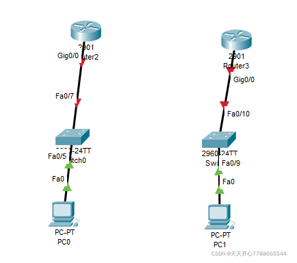
第二步,左键点击2 然后关掉电脑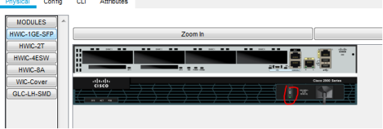
第三步,在插入 hwic-2t 的同时,打开开关。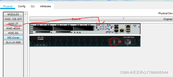
第四步,使用根根3(未如上图所示)重复此进程。
第五步是连接时钟线或橙色线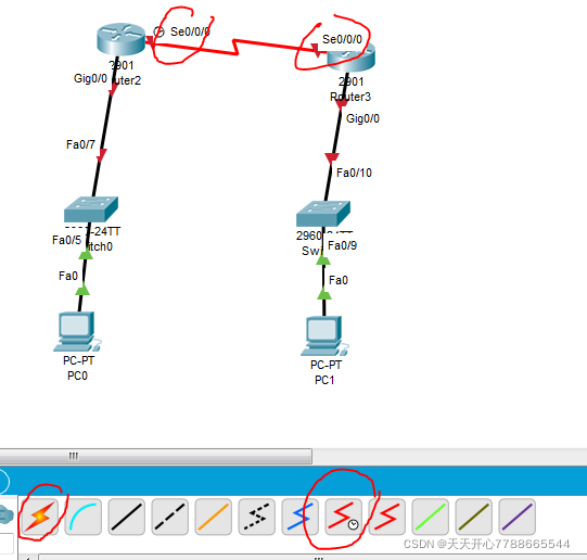
第六,配置 PC 0 的 IP 地址 。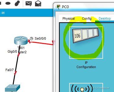
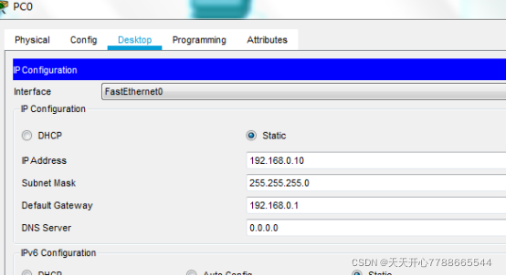
第7步:将pc1设为与第6步相同的数值(这与图表不符)。
步骤 8 配置路由器 g0/ 0ip 地址, 配置子网遮罩, 并启用接口 。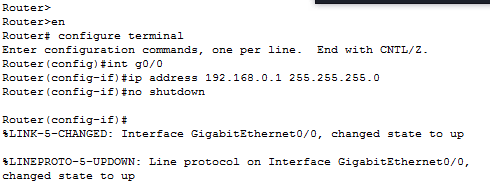
步骤9对替代路径适用同样的逻辑。
步骤10:配置序列端口的 IP 地址和子网遮罩 。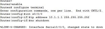
步骤11:以与第十步相同的方式配置另一序列。
步骤12:建立循环网络圈圈与圈圈与圈圈与圈圈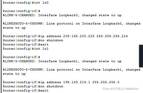 步骤13, 按表根2 配置 pc1 子页面代码的路线, 然后进入下一步 。
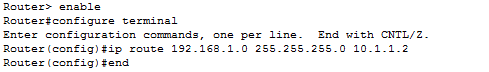
第14步,按表根3 配置 pc0 子网遮罩的路径,然后进入下一阶段。
这些是课堂程序,有些实验性研究仍然需要澄清。 )
(extra) 第15步分发设备名称
 (此外,第十六部分停止 dns 搜索开关,指定 Cisco 作为控制器和 vty 密码,并将运行配置保存到启动配置文件 。)
第17步,“钟速率”(Dec)为“r3”设置,无需“静态”理由,但请将其纳入试验报告。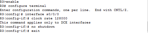
(c) 步骤18:将R1循环的静态线路移回地址。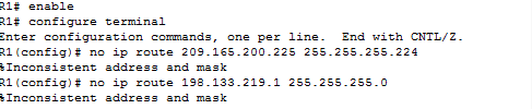
(可选)第19步将静态路线设为0/0。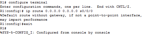
(c) pc-a ping pc-a ping pc-a ping pc-a ping pc-a ping (c) pc-a ping (c) pc-a ping (c) pc-a ping
pc-a ping198.133.219.1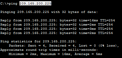
本文由 在线网速测试 整理编辑,转载请注明出处。