实验8-1RIP v2路由配置(执行步骤在文章的最后18步)
最后更新:2022-05-10 22:12:24 手机定位技术交流文章
- 实验设置基本 RIPv2 流程图
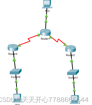
拓扑
地址分配表
IP 地址 IP 子网罩默认网关设备接口
R1 G0/1 172.30.10.1 255.255.255.0 N/A
S0/0/0 (DCE) 10.1.1.1 255.255.255.252 N/A
R2 G0/0 209.165.201.1 255.255.255.0 N/A
S0/0/0 10.1.1.2 255.255.255.252 N/A
S0/0/1 (DCE) 10.2.2.2 255.255.255.252 N/A
R3 G0/1 172.30.30.1 255.255.255.0 N/A
S0/0/1 10.2.2.1 255.255.255.252 N/A
S1 N/A VLAN 1 N/A N/A
S3 N/A VLAN 1 N/A N/A
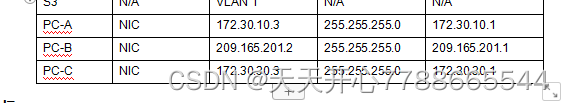
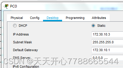
PC-A NIC 172.30.10.3 255.255.255.0 172.30.10.1
PC-B NIC 209.165.201.2 255.255.255.0 209.165.201.1
PC-C NIC 172.30.30.3 255.255.255.0 172.30.30.1
目标
构成部分1:基本联网和设备安装
第2部分:设置和测试RIPv2 路线
设置和测试RIPv2合规路由器。
配置被动接口。
检查路由表。
禁用自动总结。
配置默认路由。
* 检查端对端连接。
背景/场景
在小型网络中,IP2版本2(RIPv2)用于IPv4地址。根据RFC 1723的定义,RIPv2是没有等级的远距离病媒路线协议。由于RIPv2是不具约束力的协定,路径更新中将包含子网遮罩。默认情况下,RIPv2自动总结主要网络边界上的网络。禁用自动总结后,RIPv2 在边境路由器上,网络不再被归纳为阶级地址。
在此实验中,您将使用 RIPv2 路线配置网络, 停止自动汇总, 分配默认路线, 使用 CLI 命令显示和测试 RIP 路线信息 。
N.B. Cisco IOS 版本15. Cisco 1941年2(4)M3(通用K9图像)的综合多业务路由器(ISR),用于CCNA亲手操作练习。Cisco IOS 版本15. Cisco Catalyst 2960系列开关已经使用。还有许多其他路由器、开关和Cisco IOS版本。根据模型和Cisco IOS版本,现有说明和产出可能不同于试验中显示的说明和产出。关于正确的接口标识,请见试验结束时的路由器界面总表。
注:如果路由器和开关启动配置未擦除,请与教师联系。
所需资源
3 路由器(支持Cisco IOS 15) 2(4)(4)M3 General 图像 Cisco 1941 或类似路由器)
**2开关(在Cisco IOS 15版支持下)。 (2) Lanbasek9 图像需要 Cisco 2960 或类似开关。
3台个人电脑(运行Windows 7、Vista或XP,能够运行终端模拟软件,如Terra Terrance)
控制台电缆用于通过控制台端口配置 Cisco IOS 设备 。
泰特展示以太网和序列线。
构成部分1:基本联网和设备安装
第1部分涉及建立顶级和配置基本参数的网络。
步骤 1: 创建在上到下图中描述的网络 。
步骤2:重新装载和启动路由器和开关。
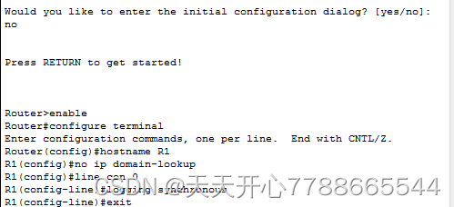
第3步:完成每个路由器和开关的基本配置。
禁用 DNS 搜索
b. 将装置的名称作为Tartao示范。
c.配置密码加密。
类被指定为特许 EXEC 密码 。
e. 我不知道你在说什么。指定 Cisco 作为控制表和Vty 密码。
我不确定您在说什么。 配置一个 MOTD 标签线, 告诉用户: 禁止未经授权的访问 。
对不起,g. 设置同步记录在控制台线上。
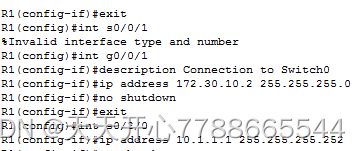
我不知道你在说什么 H. Configures all interfects with the address 提供地址分配表中的地址
我不确定你在说什么。设置每个接口的描述, 显示IP 地址 。
我不知道你在说什么 J 如有必要 配置DCE序列界面的时钟频率
我不懂你的意思, K. C. 选择运行设置到启动配置 。
第四步:设置个人电脑主机。
个人电脑主机地址详情请见地址分配表。
第五步:检查连接。
PC 此时无法相互执行 ping 函数 。
每个工作站应能对连接的路由器进行铺设操作,如果需要,核查和弥补任何缺陷。
b. 路由器应能够相互配合,必要时核查和弥补任何缺陷。
第2部分:设置和测试RIPv2 路线
在第2部分,您将为网络中的所有路由器设置 RIPv2 路线, 然后验证路线表是否已经成功更新。 在测试 RIPv2 之后, 您必须关闭自动校验, 配置默认路线, 然后验证端到端连接建立 2, 您将设置网络中所有路由器的 RIPv2 路线, 然后验证路线表是否已经成功更新。 在测试 RIPv2 之后, 您必须关闭自动校验, 配置默认路线, 然后验证端到端连接 。
第1步 设置RIPv2路线
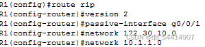
在R1上,设置RIPv2作为路线协议,并通知适当的网络。
R1# config t
R1(config)# router rip
R1(config-router)# version 2
R1(config-router)# passive-interface g0/1
R1(config-router)# network 172.30.0.0
R1(config-router)# network 10.0.0.0
被动界面指令禁止给定界面更新其路径, 从而阻止局域网内不想要的线路交通的发展, 然而, 分配给接口的网络仍会接到其他界面消除界面指令的更改通知, 从而禁止给定界面更新路径, 从而阻止局域网内不想要的线路交通的发展, 但是, 分配给该接口的网络仍然会接到其他界面的更新通知 。
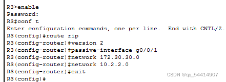
b. 在R3上,使用网络语句配置RIPv2,添加必要的网络,防止局域网接口的修改。
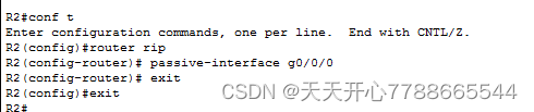
c. 在R2上,在未通知网络的情况下配置RIPv2。
注:由于连接该接口的网络不知情,有关R2的G0/0接口不必是被动接口。
步骤2:审查网络的现状。
a. 您可以使用 show ip 接口短命令快速验证 R2 上两个链条的状态 。
R2# show ip interface brief
Interface IP-Address OK? Method Status Protocol
Embedded-Service-Engine0/0 unassigned YES unset administratively down down
GigabitEthernet0/0 209.165.201.1 YES manual up up
GigabitEthernet0/1 unassigned YES unset administratively down down
Serial0/0/0 10.1.1.2 YES manual up up
Serial0/0/1 10.2.2.2 YES manual up up
b. 检查个人电脑之间的联系。
PC- B 上的 ping 程序能否在 PC- A 上进行? 为什么不能? 数据从 R1 传送到 R2 无法传送到 PC- B 。
你能为PC -C做个PC -A的Ping操作吗?
PC -B上的Ping程序能否在PC -C上进行?不。为什么一旦R3向R2传送了信息,我就不能去PC -B?
PC-A上的Ping操作能否在PC-C上进行?有可能吗?为什么?
c. 检查RIPv2是否在路由器上活动。
要检查 RIPv2 活动, 请使用调试 ip 抓取, 显示 ip 协议, 并显示运行命令。 R1 上的显示 ip 协议命令的输出如下 。
R1# show ip protocols
Routing Protocol is “rip”
Outgoing update filter list for all interfaces is not set
Incoming update filter list for all interfaces is not set
Sending updates every 30 seconds, next due in 7 seconds
Invalid after 180 seconds, hold down 180, flushed after 240
Redistributing: rip
Default version control: send version 2, receive 2
Interface Send Recv Triggered RIP Key-chain
Serial0/0/0 2 2
Automatic network summarization is in effect
Maximum path: 4
Routing for Networks:
10.0.0.0
172.30.0.0
Passive Interface(s):
GigabitEthernet0/1
Routing Information Sources:
Gateway Distance Last Update
10.1.1.2 120
Distance: (default is 120)
在对 R2 发布调试ip 开关命令后,哪些信息可用于确认 RIPv2 活动?
遵循特殊 EXEC 模式建议, 在看到调试输出后, 发布一个不调试全部命令 。
在使用 R3 上的显示运行命令后,哪些信息可用于确认 RIPv2 活动?
(d) 确认路线的自补。
一个微不足道的网络通过局域网连接到R1和R3。R2路线表显示了通往16个网络的两条等价路线。R2 只显示最常见的网络地址类型 。网络的子网将不显示 。
R2# show ip route
<省略部分输出>
10.0.0.0/8 is variably subnetted, 4 subnets, 2 masks
C 10.1.1.0/30 is directly connected, Serial0/0/0
L 10.1.1.2/32 is directly connected, Serial0/0/0
C 10.2.2.0/30 is directly connected, Serial0/0/1
L 10.2.2.2/32 is directly connected, Serial0/0/1
R 172.30.0.0/16 [120/1] via 10.2.2.1, 00:00:23, Serial0/0/1
[120/1] via 10.1.1.1, 00:00:09, Serial0/0/0
209.165.201.0/24 is variably subnetted, 2 subnets, 2 masks
C 209.165.201.0/24 is directly connected, GigabitEthernet0/0
L 209.165.201.1/32 is directly connected, GigabitEthernet0/0
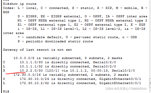
R1只出现在网络的子网中,R1没有通过子网路线到达R3。
R1# show ip route
<省略部分输出>
10.0.0.0/8 is variably subnetted, 3 subnets, 2 masks
C 10.1.1.0/30 is directly connected, Serial0/0/0
L 10.1.1.1/32 is directly connected, Serial0/0/0
R 10.2.2.0/30 [120/1] via 10.1.1.2, 00:00:21, Serial0/0/0
172.30.0.0/16 is variably subnetted, 2 subnets, 2 masks
C 172.30.10.0/24 is directly connected, GigabitEthernet0/1
L 172.30.10.1/32 is directly connected, GigabitEthernet0/1
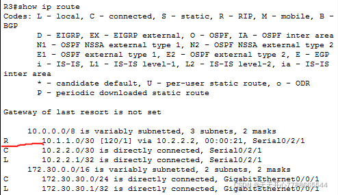
R3只出现在网络的子网中。 R3没有通过子网转到 R1 。
R3# show ip route
<省略部分输出>
10.0.0.0/8 is variably subnetted, 3 subnets, 2 masks
C 10.2.2.0/30 is directly connected, Serial0/0/1
L 10.2.2.1/32 is directly connected, Serial0/0/1
R 10.1.1.0/30 [120/1] via 10.2.2.2, 00:00:23, Serial0/0/1
172.30.0.0/16 is variably subnetted, 2 subnets, 2 masks
C 172.30.30.0/24 is directly connected, GigabitEthernet0/1
L 172.30.30.1/32 is directly connected, GigabitEthernet0/1
在 R2 上运行调试 ip 抓取命令, 以在 RIP 更新中检测和列出 R3 从 R3 接收的路径 。
172.30.30…0/24
第三步 自动总结关闭
a..\..\..\
R1(config)# router rip
R1(config-router)# no auto-summary
b. 执行清除 ip 路径* 命令,从表格中删除路径。
R1(config-router)# end
R1# clear ip route *
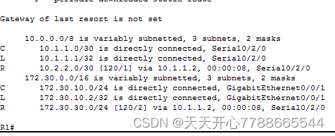
c. 检查路线表。请注意,清理路线表需要时间来建立路线表。
所有三个路线表现在都应包含连接R1和R3的局域网。
R2# show ip route
<省略部分输出>
Gateway of last resort is not set
C 10.1.1.0/30 is directly connected, Serial0/0/0
L 10.1.1.2/32 is directly connected, Serial0/0/0
C 10.2.2.0/30 is directly connected, Serial0/0/1
L 10.2.2.2/32 is directly connected, Serial0/0/1
172.30.0.0/16 is variably subnetted, 3 subnets, 2 masks
R 172.30.0.0/16 [120/1] via 10.2.2.1, 00:01:01, Serial0/0/1
[120/1] via 10.1.1.1, 00:01:15, Serial0/0/0
R 172.30.10.0/24 [120/1] via 10.1.1.1, 00:00:21, Serial0/0/0
R 172.30.30.0/24 [120/1] via 10.2.2.1, 00:00:04, Serial0/0/1
209.165.201.0/24 is variably subnetted, 2 subnets, 2 masks
C 209.165.201.0/24 is directly connected, GigabitEthernet0/0
L 209.165.201.1/32 is directly connected, GigabitEthernet0/0
R1# show ip route
<省略部分输出>
Gateway of last resort is not set
C 10.1.1.0/30 is directly connected, Serial0/0/0
L 10.1.1.1/32 is directly connected, Serial0/0/0
R 10.2.2.0/30 [120/1] via 10.1.1.2, 00:00:12, Serial0/0/0
172.30.0.0/16 is variably subnetted, 3 subnets, 2 masks
C 172.30.10.0/24 is directly connected, GigabitEthernet0/1
L 172.30.10.1/32 is directly connected, GigabitEthernet0/1
R 172.30.30.0/24 [120/2] via 10.1.1.2, 00:00:12, Serial0/0/0
R3# show ip route
<省略部分输出>
10.0.0.0/8 is variably subnetted, 3 subnets, 2 masks
C 10.2.2.0/30 is directly connected, Serial0/0/1
L 10.2.2.1/32 is directly connected, Serial0/0/1
R 10.1.1.0/30 [120/1] via 10.2.2.2, 00:00:23, Serial0/0/1
172.30.0.0/16 is variably subnetted, 2 subnets, 2 masks
C 172.30.30.0/24 is directly connected, GigabitEthernet0/1
L 172.30.30.1/32 is directly connected, GigabitEthernet0/1
R 172.30.10.0 [120/2] via 10.2.2.2, 00:00:16, Serial0/0/1
d. 在 R2 上,使用调试ip 抓取命令来核查 RIP 更新 。
R2# debug ip rip
60秒内没有调试 IP 规则指令发送 。
R3 RIP更新中包括哪些线条?
172.30.30.0/24
路径更新是否现在包含子网遮罩? 此不包含
步骤4:配置和传播默认的互联网接入路线。
a.在 R2 上,使用静态路径构建有 ip 根命令的网络 。这将将任何未知地址发送至位于PC-B上的R2 G0/0。这通过配置 R2 路由器的最后选择网关来复制互联网。
R2(config)# ip route 0.0.0.0 0.0.0.0 209.165.201.2
b. 如果RIP配置包括一项默认信息订单,R2将告知该路线的其他路由器。
R2(config)# router rip
R2(config-router)# default-information originate
第5步:检查路线设置。
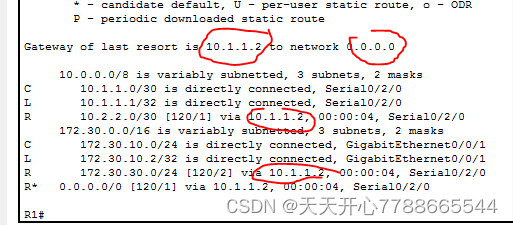
参见R1上的路线表。
R1# show ip route
<省略部分输出>
Gateway of last resort is 10.1.1.2 to network 0.0.0.0
R* 0.0.0.0/0 [120/1] via 10.1.1.2, 00:00:13, Serial0/0/0
10.0.0.0/8 is variably subnetted, 3 subnets, 2 masks
C 10.1.1.0/30 is directly connected, Serial0/0/0
L 10.1.1.1/32 is directly connected, Serial0/0/0
R 10.2.2.0/30 [120/1] via 10.1.1.2, 00:00:13, Serial0/0/0
172.30.0.0/16 is variably subnetted, 3 subnets, 2 masks
C 172.30.10.0/24 is directly connected, GigabitEthernet0/1
L 172.30.10.1/32 is directly connected, GigabitEthernet0/1
R 172.30.30.0/24 [120/2] via 10.1.1.2, 00:00:13, Serial0/0/0
路径表无法确定R1和R3共享的分裂子网网络是否有互联网交通路径。
检查路径列表以查看它是否存在*
b. R2上,查看路线表。
路线表如何指导互联网的流通?
S* 0.0.0.0/0 [1/0] via 209.165.201.2
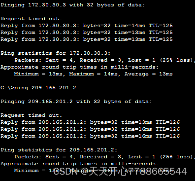
第六步:检查连接。
3 5 5 5 5 5 5 5 5 5 5 5 5 5 5 5 5 5 5 5 5 5 5 5 5 5 5 5 5 5 5 5 5 5 5 5 5 5 5 5 5 5 5 5 5
你让小叮当工作了吗?
b. PC-A和PC-C之间的连接,检查网络主机在定义子网之后的连接情况。
你让小叮当工作了吗?注意:可能需要禁用 PC 防火墙。
路由器接口摘要表
路由器接口摘要
以太网接口 # 1 以太网接口 # 2 法律接口 # 1 法律接口 # 2 路由器模型
1800 Fast Ethernet 0/0 (F0/0) Fast Ethernet 0/1 (F0/1) Serial 0/0/0 (S0/0/0) Serial 0/0/1 (S0/0/1)
1900 Gigabit Ethernet 0/0 (G0/0) Gigabit Ethernet 0/1 (G0/1) Serial 0/0/0 (S0/0/0) Serial 0/0/1 (S0/0/1)
2801 Fast Ethernet 0/0 (F0/0) Fast Ethernet 0/1 (F0/1) Serial 0/1/0 (S0/1/0) Serial 0/1/1 (S0/1/1)
2811 Fast Ethernet 0/0 (F0/0) Fast Ethernet 0/1 (F0/1) Serial 0/0/0 (S0/0/0) Serial 0/0/1 (S0/0/1)
2900 Gigabit Ethernet 0/0 (G0/0) Gigabit Ethernet 0/1 (G0/1) Serial 0/0/0 (S0/0/0) Serial 0/0/1 (S0/0/1)
注意:学习如何设置路由器,检查接口以确定路由器的类型及其拥有的接口数量。我们无法包括所有路由器装置。下表列出了与Tainet和序列接口相结合的设备代号。本表格中没有其它类型的接口 。然而,真正的路由器可能有更多的接口。考虑ISDN BRI 接口。括号之间的字符串是商定的缩略语,要代表接口,请使用 Cisco IOS 命令。
第三部分:设备设置
路由器 R1
R1# show run
Building configuration…
Current configuration : 1787 bytes
!
version 15.2
service timestamps debug datetime msec
service timestamps log datetime msec
no service password-encryption
!
hostname R1
!
boot-start-marker
boot-end-marker
!
enable secret 4 06YFDUHH61wAE/kLkDq9BGho1QM5EnRtoyr8cHAUg.2
!
no aaa new-model
!
no ip domain lookup
ip cef
ipv6 unicast-routing
ipv6 cef
!
multilink bundle-name authenticated
!
!
redundancy
!
interface Embedded-Service-Engine0/0
no ip address
shutdown
!
interface GigabitEthernet0/0
no ip address
shutdown
duplex auto
speed auto
!
interface GigabitEthernet0/1
description R1 LAN
ip address 172.30.10.1 255.255.255.0
duplex auto
speed auto
ipv6 address FE80::1 link-local
ipv6 address 2001:DB8:ACAD:A::1/64
ipv6 rip Test1 enable
!
interface Serial0/0/0
description Link to R2
ip address 10.1.1.1 255.255.255.252
ipv6 address FE80::1 link-local
ipv6 address 2001:DB8:ACAD:12::1/64
ipv6 rip Test1 enable
clock rate 2000000
!
interface Serial0/0/1
no ip address
shutdown
!
router rip
version 2
passive-interface GigabitEthernet0/1
network 10.0.0.0
network 172.30.0.0
no auto-summary
!
ip forward-protocol nd
!
no ip http server
no ip http secure-server
!
ipv6 router rip Test1
!
control-plane
!
banner motd ^CUnauthorized access is strictly prohibited.^C
!
line con 0
password 7 045802150C2E
logging synchronous
login
line aux 0
line 2
no activation-character
no exec
transport preferred none
transport input all
transport output pad telnet rlogin lapb-ta mop udptn v120 ssh
stopbits 1
line vty 0 4
password 7 060506324F41
login
transport input all
!
scheduler allocate 20000 1000
!
end
路由器 R2
R2#show run
Building configuration…
Current configuration : 2073 bytes
!
version 15.2
service timestamps debug datetime msec
service timestamps log datetime msec
no service password-encryption
!
hostname R2
!
boot-start-marker
boot-end-marker
!
enable secret 4 06YFDUHH61wAE/kLkDq9BGho1QM5EnRtoyr8cHAUg.2
!
no aaa new-model
!
no ip domain lookup
ip cef
ipv6 unicast-routing
ipv6 cef
!
!
!
!
redundancy
!
interface Embedded-Service-Engine0/0
no ip address
shutdown
!
interface GigabitEthernet0/0
description R2 LAN
ip address 209.165.201.1 255.255.255.0
duplex auto
speed auto
ipv6 address FE80::2 link-local
ipv6 address 2001:DB8:ACAD:B::1/64
!
interface GigabitEthernet0/1
no ip address
shutdown
duplex auto
speed auto
!
interface Serial0/0/0
description Link to R1
ip address 10.1.1.2 255.255.255.252
ipv6 address FE80::2 link-local
ipv6 address 2001:DB8:ACAD:12::2/64
ipv6 rip Test2 enable
ipv6 rip Test2 default-information originate
!
interface Serial0/0/1
description Link to R3
ip address 10.2.2.2 255.255.255.252
ipv6 address FE80::2 link-local
ipv6 address 2001:DB8:ACAD:23::2/64
ipv6 rip Test2 enable
ipv6 rip Test2 default-information originate
clock rate 2000000
!
router rip
version 2
network 10.0.0.0
default-information originate
no auto-summary
!
ip forward-protocol nd
!
no ip http server
no ip http secure-server
!
ip route 0.0.0.0 0.0.0.0 209.165.201.2
!
ipv6 route ::/64 2001:DB8:ACAD:B::B
ipv6 router rip Test2
!
control-plane
!
banner motd ^CUnauthorized access is strictly prohibited.^C
!
line con 0
password 7 0822455D0A16
logging synchronous
login
line aux 0
line 2
no activation-character
no exec
transport preferred none
transport input all
transport output pad telnet rlogin lapb-ta mop udptn v120 ssh
stopbits 1
line vty 0 4
password 7 110A1016141D
login
transport input all
!
scheduler allocate 20000 1000
!
end
路由器 R3
R3#show run
Building configuration…
Current configuration : 1847 bytes
!
version 15.2
service timestamps debug datetime msec
service timestamps log datetime msec
no service password-encryption
!
hostname R3
!
boot-start-marker
boot-end-marker
!
enable secret 4 06YFDUHH61wAE/kLkDq9BGho1QM5EnRtoyr8cHAUg.2
!
no aaa new-model
memory-size iomem 15
!
no ip domain lookup
ip cef
ipv6 unicast-routing
ipv6 cef
!
multilink bundle-name authenticated
!
!
redundancy
!
interface Embedded-Service-Engine0/0
no ip address
shutdown
!
interface GigabitEthernet0/0
no ip address
shutdown
duplex auto
speed auto
!
interface GigabitEthernet0/1
description R3 LAN
ip address 172.30.30.1 255.255.255.0
duplex auto
speed auto
ipv6 address FE80::3 link-local
ipv6 address 2001:DB8:ACAD:C::3/64
ipv6 rip Test3 enable
!
interface Serial0/0/0
no ip address
shutdown
clock rate 2000000
!
interface Serial0/0/1
description Link to R2
ip address 10.2.2.1 255.255.255.252
ipv6 address FE80::3 link-local
ipv6 address 2001:DB8:ACAD:23::3/64
ipv6 rip Test3 enable
!
router rip
version 2
passive-interface GigabitEthernet0/1
network 10.0.0.0
network 172.30.0.0
no auto-summary
!
ip forward-protocol nd
!
no ip http server
no ip http secure-server
!
ipv6 router rip Test3
!
control-plane
!
banner motd ^CUnauthorized access is strictly prohibited.^C
!
line con 0
password 7 02050D480809
logging synchronous
login
line aux 0
line 2
no activation-character
no exec
transport preferred none
transport input all
transport output pad telnet rlogin lapb-ta mop udptn v120 ssh
stopbits 1
line vty 0 4
password 7 14141B180F0B
login
transport input all
!
scheduler allocate 20000 1000
!
end
第一步
完成下图所示的拓扑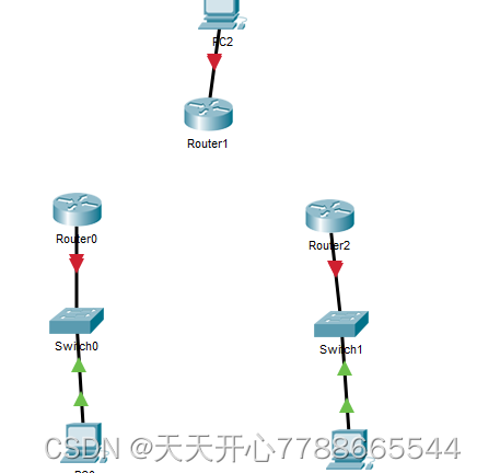
第二步是打开路由器的节点,只放置其中的一个节点,如下图所示。
关闭绿色电源,然后把它放在 nim -2t 并打开它。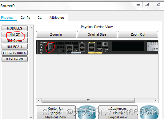
最终拓扑图如下: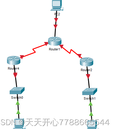
第3步:设置pc机床地址、子网膜和网关(只有一两个将填写在同一表格上)。
第四步:
配置路由器的名称、平台着陆基地、IP地址和接口。
一步一步跟着表格,然后重复其他两个。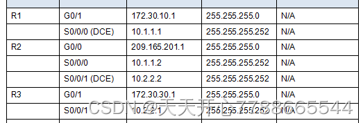
三个路由器应设置如下图所示。
第5步:调整路由器设置(仅一次或两次重复)
配置密码加密。
类被指定为特许 EXEC 密码 。
Cisco指定为控制表密码和 vty 密码。
配置一个 MOTD 标签线, 提醒用户: 禁止未经授权的访问 。
如有必要,配置 DDCE 序列界面的时钟频率 。
我不懂你的意思, K. C. 选择运行设置到启动配置 。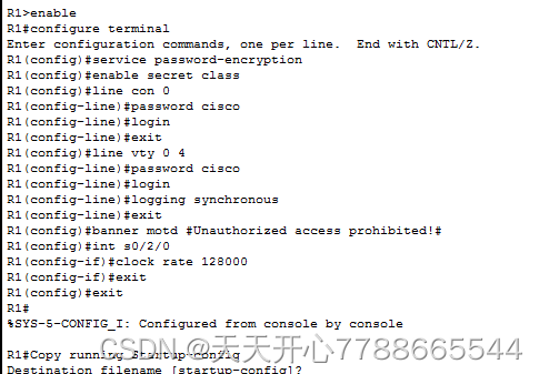
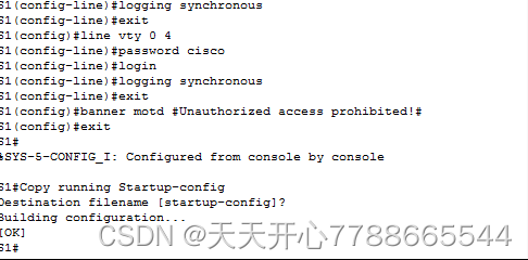
第6步:基本总机配置(只做一个,然后重复)
禁用 DNS 查看 。
配置设备名称为 Tartao 演示 。
配置密码加密。
类被指定为特许 EXEC 密码 。
Cisco指定为控制表密码和 vty 密码。
配置一个 MOTD 标签线, 提醒用户: 禁止未经授权的访问 。
设置控制台线同步记录 。
运行中的配置已被复制到启动配置 。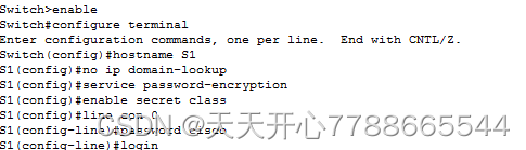
第七步是配置 ripv2 路径 。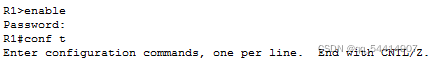
这里缺少了两个语句
network 10.1.1.0
network 10.2.2.0
步骤8:在 r2 上显示 IP 界面简报, 以加速这两个链条的状态 。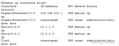
步骤9:确定R1路由器是否正在运行回转2。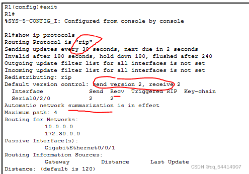
步骤10:在R2路由器上,输入调试 Ip 开关并全部解除调试。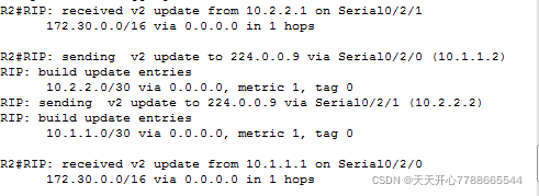
步骤11:在 R3 路由器 Exec 模式显示运行中发现了以下数据 。
步骤12:显示 R1 R2 R3 路线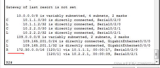
步骤13:将 r2 的调试 ip 裂纹与相关界面的裂纹比较( 这是自动摘要 ) 。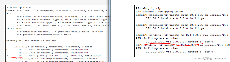
步骤14:禁用自动总结路由器,一号和二号。
(1)禁用(三个)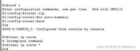
(2)检查路由表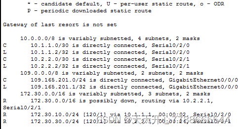

R2 检查路线更新(步骤15)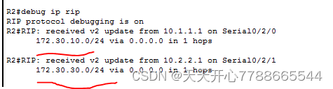
第16步:为重新指派 R2 设定默认路径。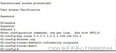
步骤 17: 在 R1 上显示 IP 根 。
步骤18:在R2上,打开路线表。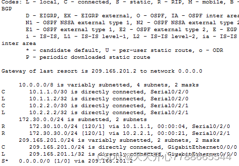
这是因为Pc0和另外两台计算机的双光线和另外两台计算机。
本文由 在线网速测试 整理编辑,转载请注明出处。